If you want to know more about the basics of electrical safety of Medical Devices, I encourage you to read this article.
I will very shortly describe what areas of interest must be covered in order to make electrical Medical Devices safe and some most basic ways to achieve this. I strongly recommend this article not only to electrical and systems engineers in Medical Industry but to any person wanting to increase their horizons on how devices should be designed and constructed. Who knows? Maybe one day you will save someone because during designing e.g., the 110-230V AC-connected to the IoT device you followed just one more safety rule, as you remembered what you read in this article?
You can use this knowledge also as good design practice, to ensure higher reliability and safety of your designs.
I will refer often to IEC 60601-1:2005+A1:2012+A2:2020 standard, as it describes general requirements for Basic Safety and Essential Performance of medical electrical equipment. This document provides more details, my target is only to make you realize the importance of electrical safety and where to look for more data.
You can also find this article in Polish.
Please note: I’m using all CAPITAL LETTERS words on purpose: whether they are used, the term is a direct reference to the standard.
(*At least according to standard IEC 60601-1:2005+A1+A2 (par. 8.7, table 3). This value refers to Normal Condition DC current).
What can I start with?
The first questions you should ask yourself are: how can a person (patient or operator) have contact? Where are any hazards in this area?
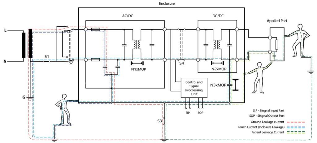
It is beneficial to start with a device block diagram that depicts all required isolations (so-called “Isolation diagram”). It can be very simplified, but allows you to notice Operator and patient leakage currents paths, e.g.:

The next step is to define the required levels of MOPP (Means of Patient Protection) and MOOP (Means of Operator Protection). Both of these MOPs (Means of Protection) are used to reduce RISK due to electric shock acc. According to the IEC 60601-1., MOOPs are required in every spot where an operator can have a contact (like housing, a.k.a. ACCESSIBLE PARTS). For MOPPs you need to specify the kind of every APPLIED PART.
If you don’t know whether an operator (e.g., Nurse, or caregiver) can touch any hazardous part, the IEC 60601-1 specifies even a test finger to evaluate for ACCESSIBLE PARTS! Please, note that this is not necessarily the same test finger as for IP testing, although generally IP3X-rated (and most IP2X) devices do not need any additional checks.
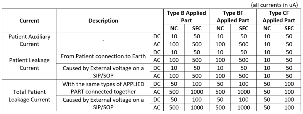
APPLIED PART type is important as relevant limits and minimum number of MOPPs are based on this qualification. Generally, there can be Type B, BF, and CF APPLIED PARTs requiring 1xMOPP or 2xMOPP. For example, Type CF requires reinforced insulation (2xMOPP) between such an Applied Part and other Patient connections of accessible parts. For details, please refer to IEC 60601-1 in its latest revision. Clause 8 gives thorough information on how to achieve protection against electrical hazards. Let’s get back to 10uA stated in the title. See Table 1 based on standard IEC 60601-1, presenting the limits below:

Some of the readers might have some kind of “certificate of qualifications” for working with High Voltage. They might be shocked by such low limits, as “general” safety limits of currents need to start at 0.5 mA (500 uA) to even “feel” the current. But remember: patients very often have some other medical conditions, cardiac problems, implants, etc., and can have contact with many Medical Devices at the same time. The IEC 60601-1 exactly defines how to measure these values, so I will refrain from going into detail on this.
What are NC and SFC?
At this point there might be some unexplained terminology:
- NC means NORMAL CONDITION
- SFC means SINGLE FAULT CONDITION
NC might sound self-explanatory, but must be taken into account together with SFC. In short: SFC is any fault detected before making any unacceptable risk or before the next component is faulty.
While making a design, you should ask yourself: if this component breaks in any way, will I detect it in time? If not, then it’s a Normal Condition – you should always assume it’s broken, unless… Well, there are some ways to deal with that 😊
What if the failure of a single element causes a domino effect and another component breaks? This is also SFC.
There are 3 basic means of handling Single Faults:
- Detection: service check or the device itself will detect failure and force action that prevents any unacceptable risk before occurring.
- Redundancy: faulty feature will not do any unacceptable risk, because there are another means of protection or parallel redundancy will ensure safety. In this case, you need to ensure which of the redundant features is working correctly.
- Negligible probability of failure: the design has a huge margin of parameters, ensuring that failure is not going to happen. For example, Reinforced insulation, Mechanical tensile safety factor of 8x, or components with High-Integrity characteristics.
What is this “unacceptable risk” that I refer to so often? Medical Device design is always based on a Risk Analysis. In theory, you might find minor inconvenience unacceptable, but also patient death could be found acceptable (if the benefits of this would be much higher, e.g., saving other lives). But for this, you must have Risk Management (ISO 14971) process up and running, which is not the topic of this article.
Assuming we know what is acceptable and what is not: does it get easier from this point? Not really, the further in the forest, the more firewood.
The most obvious way of using Detection and redundancy would be to use Software. Now, you should ask yourself one important question: Can you trust your Software? IEC 60601-1 directly refers to IEC 62304 as far as Software is concerned. And according to IEC 62304, you must always assume that your software can fail in the worst imaginable way. Especially, when concerning any safety features (e.g., Risk Control Measures). Is it a dead end? No, it’s just not as easy as it looks, process of SW Validation is required to ensure and prove that SW is reliable and safe enough. But even for non-medical systems, you should always consider evaluating the possibility of your SW failing (again: ISO 14971).
Sometimes, I propose to use an approach, which I call “safety-driven development”. Similarly to Test-Driven development, where you make your design in a way to pass some tests, here your design is supposed to pass all safety criteria. Which, of course, must be defined in the first place.
Now we know that Detection and Redundancy are not so easy and require SW validation. Then, maybe it is better to reduce the probability level of failure to improbable? Let’s push even further: let’s protect ourselves from SW risks using HW design!
Safe design (insulation)
Safe design is partly required by the standard (e.g., isolation distances, some mechanical properties), but as I said before, some can be added to prevent certain hazards.
Insulation can be achieved by combining two means:
- Insulating material by placing a barrier made from an electrical insulator. This barrier can be full (in that case it can be the only safety) or partial, so the distance still needs to be met. In the case of using an insulating material, no certification body would just believe that it is good enough. It must be sufficiently rated (if using an off-the-shelf solution) or validated.
- Distance
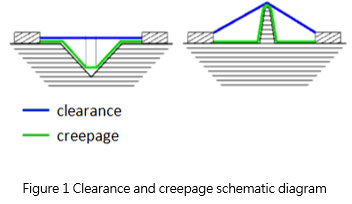
- Clearance – shortest air distance between two objects (wires, tracks, etc.).
- Creepage – shortest surface distance between two objects, but any <1 mm gap is bypassed in this case.
The definitions of distances are common for many industries, and are well depicted below:
What is very important, is that still insulation must be evaluated with a HiPot Dielectric Withstand testing. These tests are performed with dedicated testers able to source AC or DC signal – in some cases above 15 kV AC, always for at least 60 seconds. Not all requirements are that high, but usually, a 1500 V AC test is required as a minimum for every 230 V AC-powered device with just a single MOPP.
There is an urge to help yourself by using some extra insulation, but this can lead to another problem: according to IEC 60601-1, if any type of coating or potting is used, then an additional safety factor multiplier of “x1.6” is mandatory. There are many devices, for which high voltages are essential, e.g. Some plasma generators or HV cutting. Assuming only 4.0 kV peak voltage, the mentioned standard requires 17kV AC if 2xMOPP is needed, instead of “just” ~11 kV. This limitation is worth remembering.
Due to this, very often actual clearance must be higher than required by the standard, because of air ionization and arcing during the test.
But what about some lower values like 12 V and 2xMOPP? Creepage/clearance of 3.4 mm/1.6 mm is required. Creepage always needs to be higher or equal to clearance! This probably explains why all safety distances on PCBs have cutouts. Does it mean that it needs to be used for all 12 V signals? Definitely not, only for which MOP (Means Of Protection) is required. Still, you should use IPC 2221 minimum distances to have good reliability and producibility, but that’s it!
Though, there are some cases in which creepage or clearance is impossible to meet. Take for example heatsinking:
Unless the transistor case is fully insulated itself, the heatsink must be shorted into the case for safety verification. The same applies if the thermal paste is replaced with a thermal pad with an insufficient insulation rating. Then the Patient’s current is measured.
As always, the worst-case scenario must be simulated and checked.
Safe design (components)
Almost in every case, you will be using some off-the-shelf components. These can vary from the smallest passives to whole modules (like Power Supply Unit). If a component provides any safety or its failure could result in a hazardous situation, it should be generally used within its ratings. If they provide any MOP (Means Of Protection), then they should meet applicable IEC or ISO standard requirements or IEC 60601-1 requirements. This is why it is very beneficial to use certified components, even if they are certified for different industries (like household devices), as long as they meet similar acceptance criteria as actually required and pointed out within Risk Management Process.
What if a component does not provide any MOP, but still contributes to unacceptable risk in case of failure?
As I mentioned before, you can use Detection, redundancy, or negligible probability. While the first might not be possible and the second might require complicated HW and SW, there is a third. IEC 60601-1 allows the use of “Components with High-Integrity characteristics”. There is a general misconception that these include Automotive grade (AEC standards), Military grade (MIL standards), and Aerospace certified components. This misconception comes from the fact that such components generally have longer declared lifetimes in worse working conditions than generic components. While in 95% of components, this is truly what is needed from a Risk Management point of view, it is not always the case.
IEC 60601-1 clearly states that such components are: “components, where one or more characteristics ensure that its function, is fault-free concerning the safety requirements of this standard during the expected service life of the ME equipment in Normal Use and reasonably foreseeable misuse”.
To put it short:
- A component might only require 1 characteristic ensuring safety and it might happen that the AEC/MIL-certified component might not have this one. For example:
- AEC class is too low or its characteristic is not covered by any AEC standard it meets (e.g., voltage rating).
- During analysis, you might deduct that only transients are posing the risk for the component and decide that its “high-integrity” characteristic is its current and voltage rating. Therefore, the valid choice is to use e.g., capacitor with a rated voltage of 150% of its design peak value.
Summary
Safety is one of the most (if not the most) important features of not only Medical Equipment, but probably of any kind of equipment. I have only briefly described the most basic approach and have not gone into details. Still, I hope that you can benefit from this article and search for any guidance or requirements within your area of interest and make sure that only safe devices are released on the market.
Please, feel free to ask questions in the comments and state which topic you would like to know more about. Maybe I will be able to cover them in future articles.


Leave a comment