
In this article, I will attempt to provide an overview of the machine design process. The process consists of a few uncomplicated-sounding steps, but even after a cursory perusal of the subject, the list of issues grows quickly.
The design process is such a vast subject that it is virtually impossible to describe all aspects in detail in a single article. It could be said that learning machine design starts at university and actually never ends. This is the greatest thing about the work of a designer – there is always something new to invent.
Concept
The first stage of designing a machine is to work out how it will work and the overall set of necessary components that need to be used or designed. Usually, the customer already has a pre-developed process for the operation of the machine and provides it in the form of, for example, a model of a reference machine with an indication of which elements and solutions he would like to keep or develop.
If such a machine does not yet exist, the designer receives documentation outlining the steps that the production process must include. If the aim of the project is to automate production, photos or videos of the solutions currently in use are provided. On the other hand, when the project subject is a more complex machine or a non-standard production process, it is sometimes necessary to visit the customer to better understand the requirements.
First ideas
Once the scope of the project has been established, the search for solutions to build a working machine begins. Before working on the 3D model, simple sketches are created. These usually do not reflect the size and proportions of the parts; they only roughly represent the principle of operation and the main components that will be used. The sketches are done freehand, on a piece of paper.
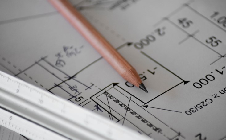
When several designers are working on a machine, they get together in meeting and similar sketches are made on a whiteboard or with the simplest applications such as Paint, PowerPoint or the Snipping Tool. An example sketch looks like this:

This is a sketch of a machine module for which there were no references – the customer was introducing a new product and there were no machine patterns to refer to. The module shown was to grip and rotate the customer’s parts.
This does not look very professional, but the vast majority of projects start with such drawings. From such a sketch, however, it can be seen that the module consists of:
- a motor,
- a coupling,
- a shaft mounted in bearings,
- a gripper,
- a structure to which these components will be attached.
Such a drawing contains enough information to start work on a simple 3D model.
Concept model
Once the designer has come to the conclusion that he has answered his initial design questions, he can move on to preliminary design in CAD. The programme in which the design is carried out is indicated by the client. Programmes such as Solid Works or Inventor are usually used for typical machines. If the customer is involved in manufacturing more complex equipment, they usually work in Siemens NX. AutoCAD, despite being synonymous with design software, is relatively rarely used for machine design.
A preliminary model has virtually the same technical value as a sketch on a piece of paper. Its sole purpose is to clearly present the idea for the machine to the customer.

As you can see from the screenshot above, the model is missing many basic components, such as screw holes. The proportions and sizes of the parts are also out of proportion, but the gripper and motor are already pre-matched to the customer’s part size and weight. This makes it possible to estimate the dimensions of the designed unit.
Models’ sources
At this stage, the most important thing is to make the idea for the machine clear, while the parts that are not designed by the designer come from suppliers approved by the customer. Models of robots, sensors, actuators, screws and other components available on the market are taken from manufacturers’ databases or dedicated sites.

It is very rare that part models are not made available before they are ordered. If such a situation does occur, simplified solids are made for the conceptual model needed, based on the technical drawings provided.
Concept approval
Once the initial modelling has been completed, a PowerPoint presentation is created where the principle of the machine is described along with an indication and general description of the components that will be used in the project. Typically, such a presentation is sent to the client prior to the meeting and together with a team of specialists on the client side.

The meeting somewhat reminiscent of a thesis defence: first, a description of the solutions is presented, then the client’s questions are answered and their concerns addressed. When the customer is satisfied with what has been presented to him, he gives the green light to proceed and the most time-consuming part of the work begins.
Designing
The main, but not the most important, part of the machine design process is the development of a 3D model, which will be used to produce manufacturing drawings, assembly drawings and further documentation. After the concept phase, the main components that will perform the activities necessary for the process to be carried out correctly – nutrunner, robot, gripper, etc. – are usually already selected.
Once the client accepts the concept, the main design work begins: searching for the best and most optimal solutions, calculating precisely the forces required to move the individual modules, positioning the components so that they can be assembled and do not interfere with each other, but are within the limits imposed by the client’s requirements.
Simplifying the whole design process to its limits, one could say that designing a machine is enclosing commercial components with parts that will hold them together and prevent the whole from falling apart. Sounds simple? Well, running a marathon sounds simple too, after all, we’ve all run a longer or shorter distance at some point, so that 42 kilometres is just a slightly longer run-up to the bus, right? As always, the devil is in the detail 😉
Golden trap
With complex machines, the main challenge is the simultaneous control of many parameters, some of which are mutually exclusive. Balancing all the factors is demanding, as one or two superior ones have to be chosen at the beginning and the rest adapted to them. However, this needs to be well thought out, as many of the assumptions made at the start of a project are impossible to change in further work, and dragging out decisions until everything is certain is impossible due to the need to order parts early with long delivery times, for example.
Even simpler projects require a great amount of forethought and foresight, as it is easy to get caught up in a dead end from which there will be no time to get out when it turns out that the first, seemingly perfect solution is impossible to achieve.
One of the causes of such situations is the trap of so-called ‘gold plating’. It is about perfecting solutions and putting a disproportionate amount of time and effort into activities that do not require such inputs. A good answer to this problem is the Swedish word ‘lagom’. It cannot be translated literally, but it means “just right, not too much, not too little“. The design does not have to be perfect, just good and functional.
Once priorities have been set, you can move on to the actual work. When designing a machine, it is worth remembering that it is not just being created for an impersonal client, but also for fitters, commissioners, machine operators and maintenance. They too will be spending a lot of time on this project, so it is worth ensuring that their work goes as smoothly as possible. Therefore, when in doubt, it is a good idea to ask them for their opinion in terms of choosing an installation approach or determining which piece of automation will work better. You can read about who fitters and commissioners are in these articles.
Cooperation with the customer
Another fixed point in the process are meetings with the client. These are usually held once a week to check on progress and to ask questions. During these meetings, the customer can, for example, communicate changes in the process that the machine in question operates, or ask for clarification of a more complex solution. The designer, for his part, has the opportunity to ask about uncertainties that arise from the specifications or to present several proposed solutions and ask the client to indicate the idea that will suit him best.
The design process follows the rhythm of these meetings. In the first few weeks, more general progress is shown, then closing in on other stages as more data flows in. At the end of this part of the process, everything that has been designed is checked: do the screws match the threads, do the holes coincide, and are there no collisions between the components, in short, is it checked that everything can be manufactured, assembled, that the machine components do not collide during operation and, above all, that everything works as it should.

As with the conceptual phase, the design phase ends with a meeting during which the finished model of the machine, including the finest details, is presented. Usually, there will be representatives from the client’s side who are responsible for design, assembly, automation and electrics.
The result of such meetings is usually the creation of a document that is a form of a model acceptance protocol, which is tantamount to an agreement to finalise the work. This document can take various forms – sometimes it is a simple e-mail, and sometimes it is a list of several pages indicating whether all requirements have been met.
Dokumentation
Once the modelling has been completed, and it has been checked whether all the elements can be made and joined together, whether they can withstand the forces that act on them, and whether there will be no collisions during the operation of the machine, it is time for the most important part of the project, which is the preparation of the manufacturing documentation. In contrary to appearances, the 3D model is only a “semi-finished product” which is used as a starting point to create drawings on the basis of which the machine will be made – let us remember that spatial models were not designed on drawing boards.

Drawings are actually made from scratch by marking the geometries to be dimensioned on the drawing. Although there are solutions to automate the drawing of parts, these are not widely used. Part of the reason for this is that drawings made in this way are often not to the customer’s standard and editing them to a state where they are acceptable can take longer than doing them without automation.
Another factor is that when drawing, it is necessary to check that all threads, dimensional tolerances and part fits are correct. Checking manually introduces another step to validate the design and so errors that may have been overlooked when checking the 3D model can be caught and corrected.
The execution documentation of the part is a critical point in the design. Even if everything looks perfect on the model and moves perfectly, whether the machine can be assembled and run correctly depends on the quality of the drawings. Incorrectly recalculating dimensional chains, giving inappropriate tolerances and fits will result in the machine modules not working properly, and fixing such errors usually involves time-consuming re-checking and correcting drawings and producing new parts.
In addition to the drawings, the designer is responsible for a number of other documents, e.g., lists of sensors with a description of their operation, cycle time diaphragm risk analysis, analysis of possible failures, their frequency and the time it takes to remove them, a schedule for replacing parts or lubrication. Once all the documents have been approved by the customer, the design process is basically over.

What’s next?
Although the mechanical layer of the project has been completed, this is not the end of the work. The part drawings are sent to the contractors, who sometimes have questions about how to make more complicated parts, or suggest a different thermo-chemical treatment (e.g., nitriding instead of hardening).
It is then necessary for the designer to decide whether the change can be made. Pneumatic, electrical and control systems also need to be designed. This is usually done by other engineers, specialized in their field, who sometimes indicate that it is better to use a different sensor or pressure regulator. It is worth listening to them, their comments and suggestions allow problems to be easily solved that can be very difficult to fix once the machine is made and assembled.
When the project enters the assembly phase, there are sometimes requests to redesign minor elements, such as brackets for mounting controls or redesigning parts to make the machine easier to maintain.
Conclusion
The machine design process is quite simple in concept but extremely complex in detail. The whole process, from concept to completion of the documentation, takes about six months. It is often very stressful, but seeing the machine in operation gives so much satisfaction that the hardships of the whole process are very quickly forgotten 😊


Leave a comment