Nowadays, Internet of Things offers plenty of ways to communicate devices with each other, turn them into systems and connect them to the Internet. To choose the right communication solution, you should consider several factors:
- maximum range,
- data bandwidth,
- energy used to transfer the data,
- legal regulations,
- and costs.
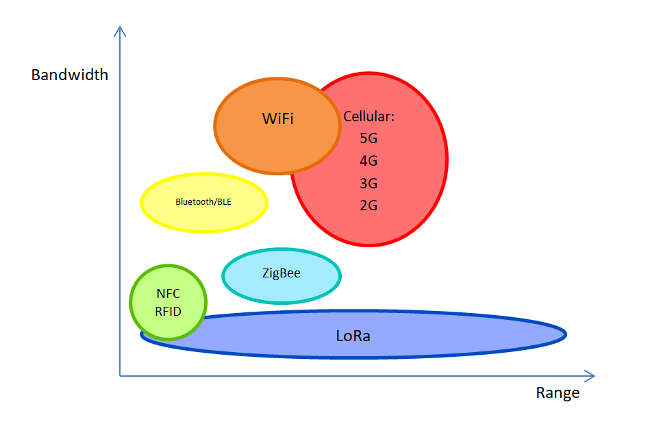
LoRa is one of the available solutions: it’s low-powered radio communication with low data bandwidth, which is theoretically considered from several bps to dozens of kbps, depending on the chosen parameters of the protocol. It is mostly designed to communicate with sensors, especially for those with a low power consumption or significant distance between sender and receiver. LoRa is owned by Semtech Corporation and operates on different frequencies which depend on countries’ legal regulations, for example, 433 MHz (Asia), 868 MHz (Europe) or 915 MHz (America).
The main goal of the article is to familiarize the reader with the LoRa radio communication protocol, its parameters and capabilities, and to demonstrate a working homemade system which uses LoRa in a real environment.
Frequencies and law regulations
The LoRa Alliance (a non-commercial organization developing LoRaWAN) has defined standardization for IoT devices which are part of the LoRaWAN network. They are based on individual country’s regulations regarding license-free frequencies. On the Internet, you will find a list of countries with applicable frequencies and legal acts.
Let’s look on Poland: we can see that we use EU433 and EU863-870 and it’s regulated by CEPT Rec. 70-03 (as of November 10, 2023).
EU433 stands for 433.05 to 434.79 MHz with support for at least 24 channels. The first 3 channels are defined on frequencies: 433.175, 433.375 and 433.575 MHz. Other channels can be freely distributed, but with the restriction of radio transmitter less than 12 dBm and the end device duty-cycle lower than 10%.
Device operating on EU863-870 should work on frequencies from 863 to 870 MHz with (at least) 24 channels of which 3 are defined on frequencies: 868.10, 868.30 and 868.50 MHz. Others are distributed with ETSI regulations.
You can find a document with more details on the LoRa Alliance website.
Possible usage
LoRa can be used where one (or more) of the following requirements shall be fulfilled:
- low power usage,
- range greater than other wireless communication mediums (Bluetooth, Wi-Fi),
- supplementing coverage where other types of communication are unavailable,
- possibility to use your own, cheap transmitters and receivers,
- no mobile data transfer fees,
- low data bandwidth.
These requirements mostly meet the needs of smart agriculture and smart cities, sensors and metering systems, and tracking or potential localization systems.
Referring to the LoRa energy consumption, most of the modules that are available on the market consume between 10 mA to 100 mA when working as a transmitter (depending on transmission parameters) and around 20 mA when working as a receiver. While not used and working in sleep mode, power consumption drops 2 µA or even 0,1 of µA.
Carrying information
FSK modulation
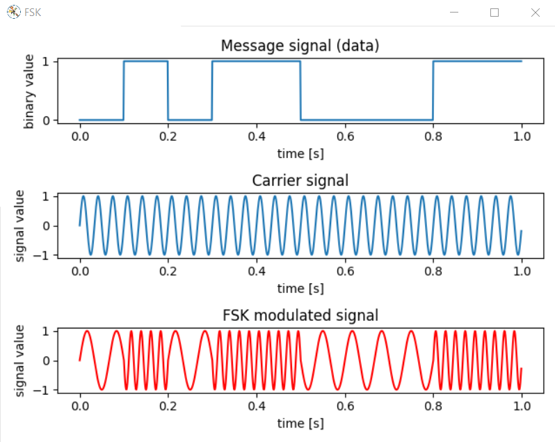
In order to send the information using some medium, there are several ways to modulate the signal like amplitude, frequency or phase modulation. It allows to send the information by changing the property (amplitude, frequency or phase) of carrier signal by message signal (carrying the information).
As an example, one of the ways of modulation is the frequency-shift key (FSK). It allows the transmission of digital information using a radio medium. In this case, the carrier frequency will be a radio signal with one frequency, and the modulated signal will carry binary information. In a modulated signal waveform, one frequency will correspond to digital 0 and the other frequency to digital 1.
LoRa case
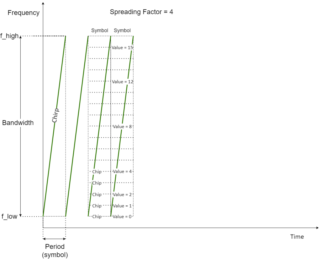
On the contrary, LoRa uses a different modulation method called Chirp Spread Spectrum (CSS). Starting from the left part of the picture let’s dive a little bit into this method. Frequency is changed from flow to fhigh (up-chirp) or fhigh to flow (down-chirp) within limits called Bandwidth during one period which makes a single symbol. This frequency change is called chirp.
A parameter called Spreading Factor (or Sweep Rate) divides the Chirp into Chips with the formula:
Chips number = 2 ^ SF
So, with the Spreading Factor = 4 there are 2 ^ 4 = 16 chips, that allows to represent 16 frequency sweep values as binary values from 0 to 15. So, SF=4 encodes 4 bits.
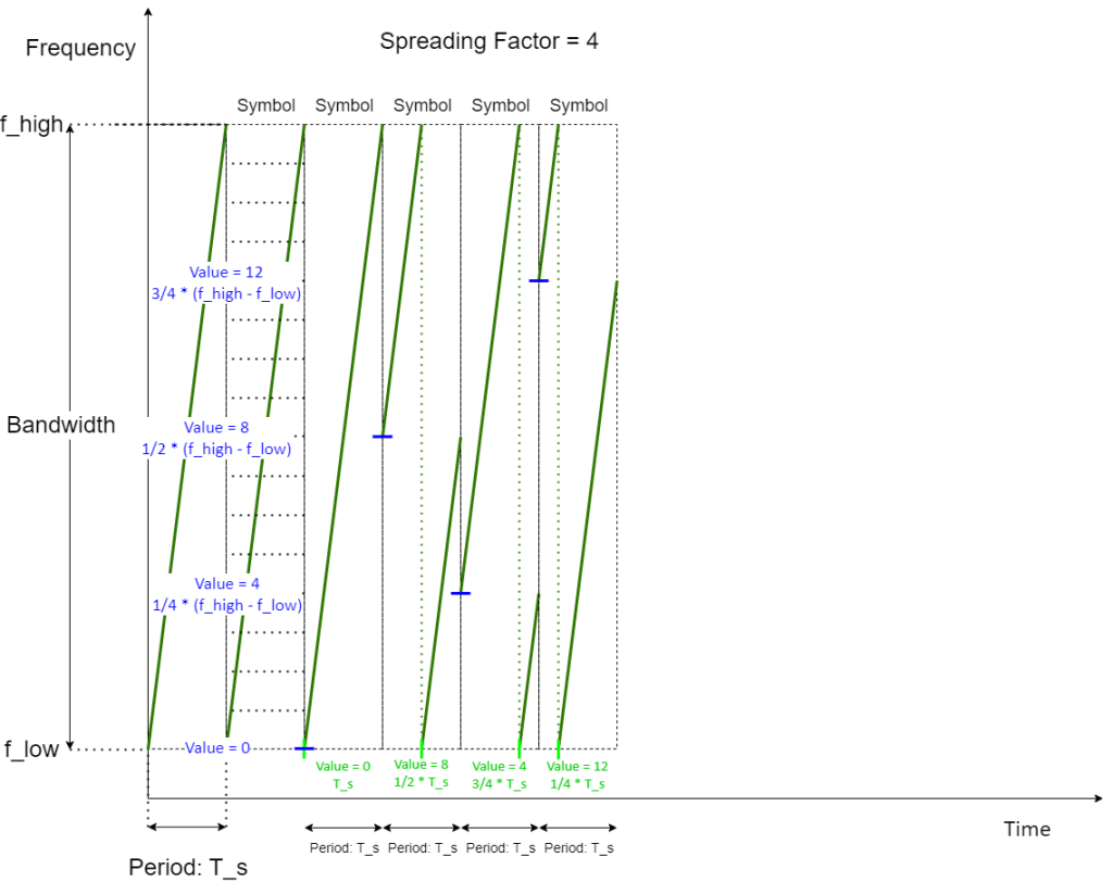
The time at which the frequency suddenly changes its value determines the digital value.
Spreading Factor
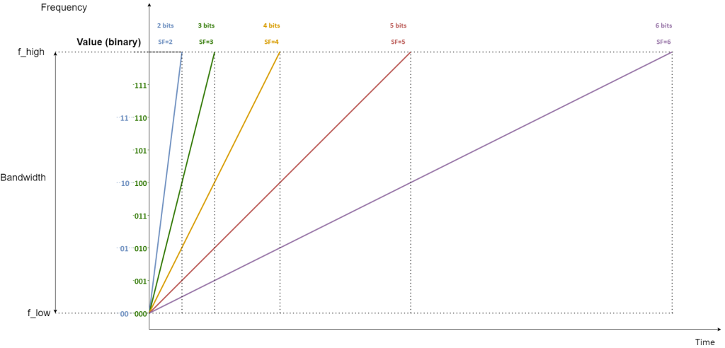
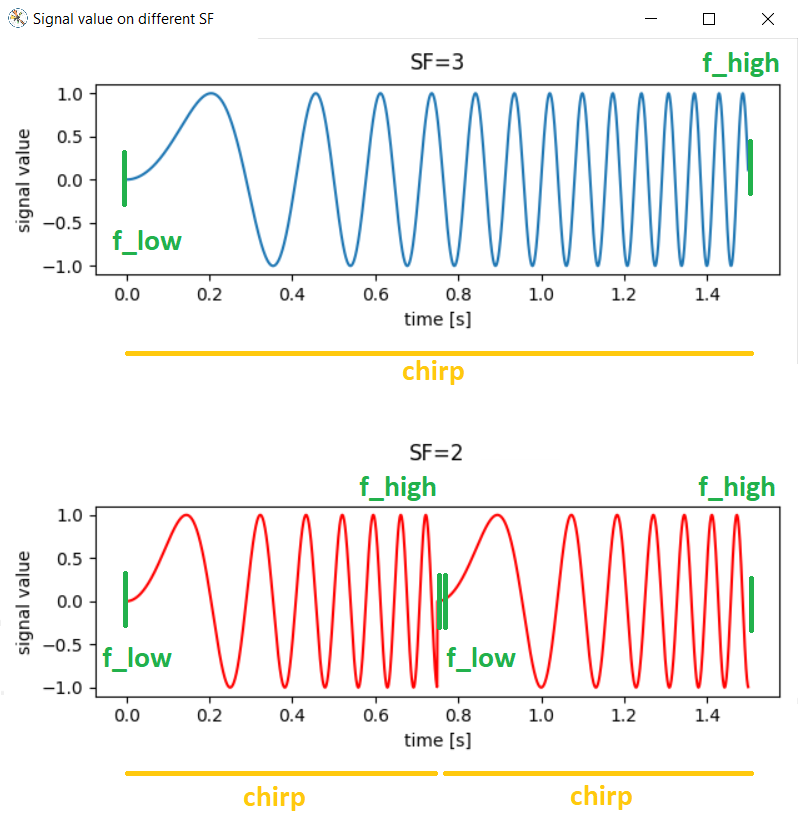
The increase of the Spreading Factor affects the number of Chips representing digital values in Chirp. But increasing the Spreading Factor by 1, at the same frequency, doubles the Chirp duration and causes the signal to increase from flow to fhigh twice as fast. This also means reducing data throughput. For example: during the duration of Chirp with SF=3, you will encode three bits, but at the same time two Chirps with SF=2 would fit into, allowing to encode 2 x 2 bits.
Spreading Factors from SF6/SF7 to SF12 are used in LoRa.
To summarize the impact of the Spreading Factor: a higher value increases the packet’s time in the air and extends the communication range, but also requires more energy to transmit data and reduces data transmission (assuming the same Bandwidth).
Bandwidth
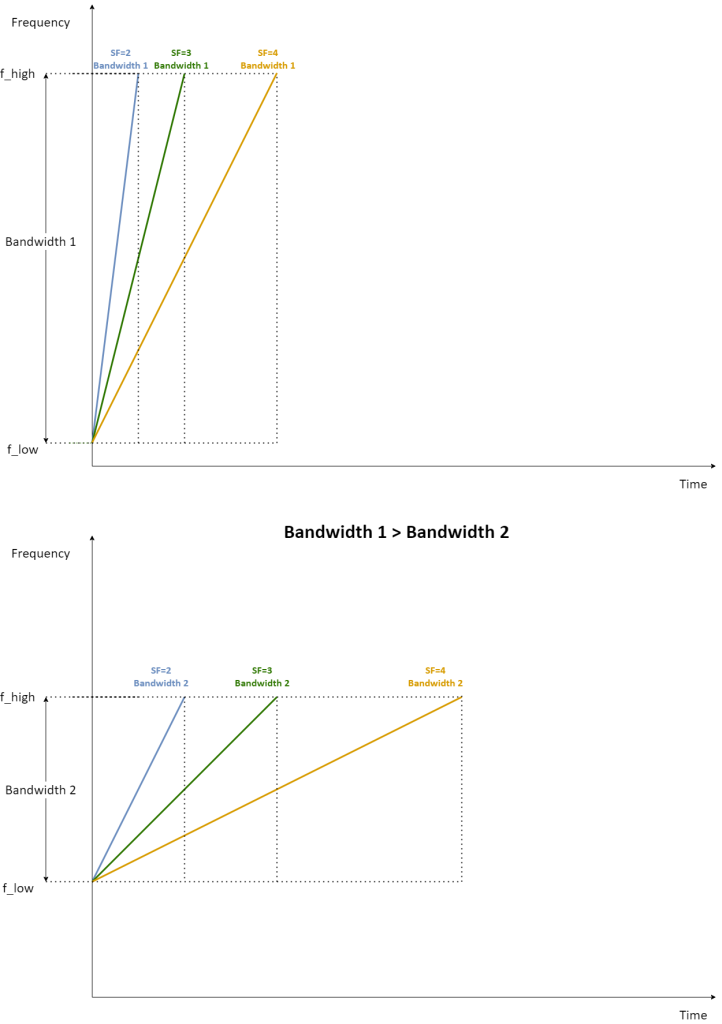
As mentioned, Bandwidth determines the range in which the Chirp frequency changes from flow to fhigh. The more we increase it, the more frequency rise/fall slope (derivative) increases, which also increases the data transfer rate at the same Spreading Factor. On the other hand, too wide Bandwidth exposes you to interference from other devices and limits its ability to transmit. Also, a narrower Bandwidth improves the transmission range.
What we often call frequency in the context of LoRa, is the central frequency of the Bandwidth. If Bandwidth is 250 kHz and the carrier frequency is 433 MHz, the chirp goes between 432,875 MHz and 433,125 MHz.
Coding Rate
There is one more modifiable parameter: Coding Rate. It is LoRa forward error correction setting (mechanism which adds supplementary bits in payload) providing an extra data quality check. There are available modes: 4/5, 4/6, 4/7, 4/8. Coding Rate 4/5 means that from 5 bits of transmitted data, 4 are used functionally (filled with data), and rest are used for error correction. 4/8 is the smallest Coding Rate, giving the longest time to send the package and having highest resistance to interference.
To summarize: changing the Coding Rate may increase the transmission quality but reduces the data rate and potentially battery life.
Result – transmission speed
Manipulating the above parameters according to the formula below:
Data rate = SF * (BW / 2 ^ SF) * CR
Gives information about desired data transmission speed.
As you can see, the setting of these factors is a tradeoff of changes in data transfer speed, range, transmission reliability and range.
| Bitrate [bps] | SF | |||||||
| CR=4/5 | 6 | 7 | 8 | 9 | 10 | 11 | 12 | |
| BW [Hz] | 7800 | 585,00 | 341,25 | 195,00 | 109,69 | 60,94 | 33,52 | 18,28 |
| 10400 | 780,00 | 455,00 | 260,00 | 146,25 | 81,25 | 44,69 | 24,38 | |
| 15600 | 1170,00 | 682,50 | 390,00 | 219,38 | 121,88 | 67,03 | 36,56 | |
| 20800 | 1560,00 | 910,00 | 520,00 | 292,50 | 162,50 | 89,38 | 48,75 | |
| 31250 | 2343,75 | 1367,19 | 781,25 | 439,45 | 244,14 | 134,28 | 73,24 | |
| 41700 | 3127,50 | 1824,38 | 1042,50 | 586,41 | 325,78 | 179,18 | 97,73 | |
| 62500 | 4687,50 | 2734,38 | 1562,50 | 878,91 | 488,28 | 268,55 | 146,48 | |
| 125000 | 9375,00 | 5468,75 | 3125,00 | 1757,81 | 976,56 | 537,11 | 292,97 | |
| 250000 | 18750,00 | 10937,50 | 6250,00 | 3515,63 | 1953,13 | 1074,22 | 585,94 | |
| 500000 | 37500,00 | 21875,00 | 12500,00 | 7031,25 | 3906,25 | 2148,44 | 1171,88 | |
Example bitrate calculated for Coding Rate = 4/5.
LoRa packet
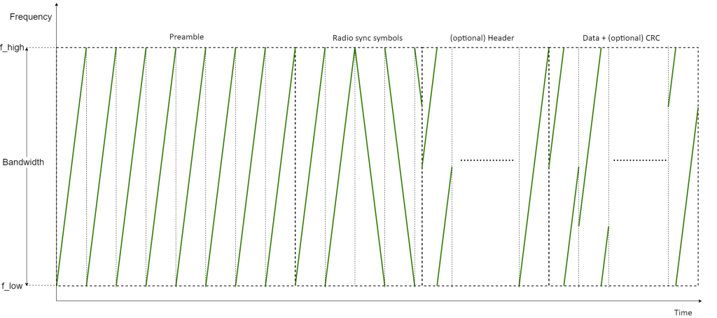

LoRa packet consists of a preamble, optional header, payload and optional payload’s CRC. Preamble contains 8 symbols by default (modifiable value) + 4.25 added by radio transmitter. Next in line is the optional header, which appears depending on whether the Explicit Header Mode option is set.
This header contains information about the length of the payload, its Coding Rate, flag determining if Cyclic Redundancy Check (CRC) is present in the payload and header CRC. The header is transmitted at a 4/8 Code Rate. Then a payload with a maximum length of 255 bytes and its optional CRC (2 bytes) is present.
Many devices transmit and receive over the air. For the LoRa receiver to be able to receive the message of the LoRa transmitting device, it should have the same preamble length and Implicit/Explicit Header Mode setting. If the radio transmitter allows it, it is also possible to scan while waiting for a preamble of maximum length. If Explicit Mode is set, the parameters regarding the payload (its length, Coding Rate, CRC) can be read by the receiver from the header. If the Implicit Header Mode is set (no header), then the payload parameters must be known in advance at the receiver and transmitter side.
Of course, the remaining parameters must include those related to physical properties: the same Frequency, Bandwidth and Spreading Factor.
LoRa vs LoRaWAN
LoRa (as opposed to LoRaWAN) provides the first (physical) layer of the standard OSI Network Model. On top of that, LoRaWAN applies the next layers, providing device, MAC and logical addressing. But this article covers only the topic of LoRa protocol usage without any encryption and how to establish a basic machine-to-machine connection. Please notice that anyone using the same connection parameters could sniff the data that you send over the air.
LoRaWAN can provide services related to adaptive parameter change, encryption and device recognition at the next layer.
Ra-01 – test case and results

When testing LoRa, I used the Ra-01 module based on SX1278. It has an attached antenna for 433 MHz, so this determines the range of used frequencies.
As a communication device, I have chosen STM32F103C8T6 as the simplest devboard.
Ra-01 is 3.3 V powered (same as chosen STM32). The board communicates via SPI, so lines MISO, MOSI, SCK and NSS (CS) are needed to establish the communication. Other exposed pins are RST (SX1278 reset pin) and optionally connected interrupt pins (DI0-DI5).
Based on my tests, if you have connectivity issues, focus initially on your carrier frequency (a lot of wireless devices may work around your environment around frequency 433MHz) and your bandwidth.
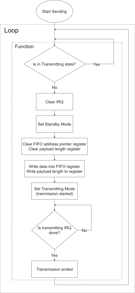
sx127x_result_t sx127x_lora_send_data(sx127x_spi_configuration_t* spi_conf, uint8_t* data, uint8_t data_size, uint8_t timeout_ms)
{
sx127x_result_t result = SX127X_STATUS_OK;
bool is_transmitting = false;
sx127x_lora_get_is_transmitting(spi_conf, &is_transmitting);
if (is_transmitting)
{
return result;
}
result = sx127x_set_op_mode(spi_conf, SX127X_OP_MODE_STANDBY);
if (result != SX127X_STATUS_OK) return result;
result = (*spi_conf->spi_write_register_function)(spi_conf->spi_hal, SX127X_REG_FIFO_ADDR_PTR, 0);
if (result != SX127X_STATUS_OK) return result;
result = (*spi_conf->spi_write_register_function)(spi_conf->spi_hal, SX127X_REG_PAYLOAD_LENGTH, 0);
if (result != SX127X_STATUS_OK) return result;
if (data_size > 255)
{
return SX127X_STATUS_WRONG_INPUT;
}
for (size_t i = 0; i < data_size; i++)
{
result = (*spi_conf->spi_write_register_function)(spi_conf->spi_hal, SX127X_REG_FIFO, data[i]);
if (result != SX127X_STATUS_OK) return result;
}
result = (*spi_conf->spi_write_register_function)(spi_conf->spi_hal, SX127X_REG_PAYLOAD_LENGTH, data_size);
if (result != SX127X_STATUS_OK) return result;
result = sx127x_set_op_mode(spi_conf, SX127X_OP_MODE_TX);
if (result != SX127X_STATUS_OK) return result;
uint8_t reg_irq_flags = 0x00;
while ((reg_irq_flags & SX127X_IRQ_TX_DONE_MASK) == 0)
{
(*spi_conf->delay_function)(10);
result = (*spi_conf->spi_read_register_function)(spi_conf->spi_hal, SX127X_REG_IRQ_FLAGS, ®_irq_flags);
if (result != SX127X_STATUS_OK) return result;
}
result = (*spi_conf->spi_write_register_function)(spi_conf->spi_hal, SX127X_REG_IRQ_FLAGS, SX127X_IRQ_TX_DONE_MASK);
return result;
}
Above I have included a proposal for sending data using Ra-01. The entire code, along with the sample configuration and project that I prepared for testing, can be found on GitHub.
Details of testing
I performed some tests in an urban environment, inside a multi-family apartment block. The transmitter was located on the first floor. The receiver was changing its position within the garage hall, from 18 to 64 meters. The signal had to overcome layers of concrete and reinforcement standards for a multi-story building. The transmitter was sending a payload of 11 bytes, trying to send them every 1 second. With the changing Spreading Factor, I tried to find the maximum transmitter-receiver distance in a straight line to which packets arrive correctly.
The transmission parameters were set according to recommendations (LoRa Alliance) for an example LoRaWAN device: frequency = 434 MHz, Bandwidth = 125 kHz, power level 12dBm. Other parameters have been set to: Coding Rate = 4/6, Explicit Mode on, CRC on.
| SF7 | SF8 | SF9 | SF10 | SF11 | SF12 | |
| Distance achieved [m] | 18 | 30 | 42 | 49 | 53 | 64 |
I also performed a distance test with the above parameters in an urban environment by placing the transmitter outside and trying to receive the signal outside. Between the transmitter and the receiver, there were multi-family buildings and industrial plants. In a straight line with SF=12 setting, I managed to get a distance of approx. 640 m. This could be improved by having a different antenna attached to the module and performing tests in less interfered environment. Anyway, the results are still satisfying.
Summary
To sum up, it is possible to achieve low-cost wireless communication using easily available, low-power and cheap equipment, using a free frequency band. It is possible to obtain quite good results, even in a noisy environment, and even without hardware modifications. The tests confirmed the operation, expectations and possibilities of parameterization of the protocol.
Sources
***
If you’re curious about embedded topics, also take a look at other articles by our experts.



Leave a comment